

Inner Grooved Copper Low Fin Tube for Heat Exchanger and Air Cooler
What is an Inner Grooved Copper Low Fin Tube?
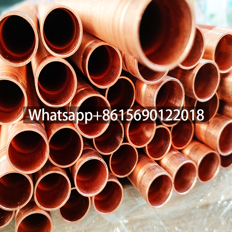
Inner Grooved Copper Low Fin Tube is also known as a steam fin tube, internal fin tube, or low-fin tube.
Inner Grooved Copper Low Fin Tube is a common heat exchange tube with threads rolled onto the inner surface and fins rolled out of the outer surface of the bare tube using a rolling roller. This is a high-efficiency heat exchange tube with both the tube and fins integrated into the same tube.


Inner Grooved Copper Low Fin Tube Materials
Standard: ASTM B359/ASME SB 359
Material: Copper T2/TP2, Cupronickel B7, Copper Nickel Iron Alloy BFe 10-1-1, BFe 30-1-1, Complex Brass HSN 70-1, HA177-2
Carbon Steel, Stainless Steel, Titanium
Inner Grooved Copper Low Fin Tube Specifications
Base Tube OD: 12-25.4mm
Base Tube Thickness: 1-1.5mm
Fin Height: Max 1.45mm
FPI: 19-50
Length: Max 25m

Function of Internally Grooved Low Fin Tubes
Internally Grooved Low Fin Tubes are typically made of copper and often feature vertical rods for easier installation.
The reinforcement of this type of internally grooved low fin tube is located on the outside of the tube. The heat transfer enhancement effect on the medium is manifested in the following ways:
The spiral fins increase the heat transfer area. Furthermore, when the shell-side medium flows over the spiral tube surface, the surface spiral fins divert the laminar edge layer, thinning the boundary layer thickness. The turbulence generated on the surface is also stronger than that of a plain tube, further reducing the boundary layer thickness. This combined effect gives internally spiraled low-fin tubes a higher heat transfer capacity.
When used for evaporation, internally spiraled low-fin tubes increase the number of bubbles formed per unit surface area, improving boiling heat transfer capacity. When used for condensation, the spiral fins significantly facilitate condensate dripping at the lower end of the tube, reducing liquid film thickness, lowering thermal resistance, and improving condensation heat transfer efficiency.
Low-fin tubes primarily rely on external fins (with a fin coefficient of 2-3) to increase the heat transfer area. Compared to bare tubes, they offer a larger surface area while consuming the same amount of metal material. While intuitively, this appears to be a primary heat transfer enhancement, it is essentially the increased heat transfer area that leads to an increase in the heat transfer coefficient. The fins delaminate the fluid layer on the heat transfer surface, increasing surface turbulence and improving heat transfer efficiency. This is considered secondary heat transfer enhancement.
The main factors influencing heat transfer enhancement on a finned surface are fin height, fin thickness, fin spacing, and the thermal conductivity of the fin material. Furthermore, since one side of the heat transfer wall is expanded to become the fin surface, convective heat transfer on the smooth side and the thermal conductivity of the base wall have a certain impact on the overall heat transfer. The fin spacing of low-finned tubes is determined based on the surface tension of the liquid and the shear force exerted on the liquid film by the flow.
Low-finned tubes also have excellent resistance to fouling. Fouling typically forms parallel flakes along the edges of the wave crests. During operation, the tube expands and contracts with temperature changes. This accordion-like expansion and contraction effect prevents fouling. On bare tubes, however, fouling forms a cylindrical layer on the tube wall, and there is no inherent mechanism to prevent fouling.
Due to the smaller number of fins, the cleaning method and difficulty of low-finned tubes are exactly the same as those of bare tubes. In addition, the low-fin tube uses ordinary smooth tube as the blank. After a simple rolling process, its mechanical strength and corrosion resistance are not inferior to the original smooth tube blank, which can fully ensure the generation of dirt. The heat exchanger can operate reliably for a long time.
Applications – Low Finned Tubes
The common application fields are:
- heat exchangers for power plants (electric, nuclear, thermal and geothermal power plants)
- high corrosive systems (condensers, evaporators, sea water desalinations, fertilizing, urea systems, ammonia, gas, corrosive acids)
- chemical and petrochemical industries
- food processing and refrigeration industries.
Package-Inner Grooved Low Finned Tubes

