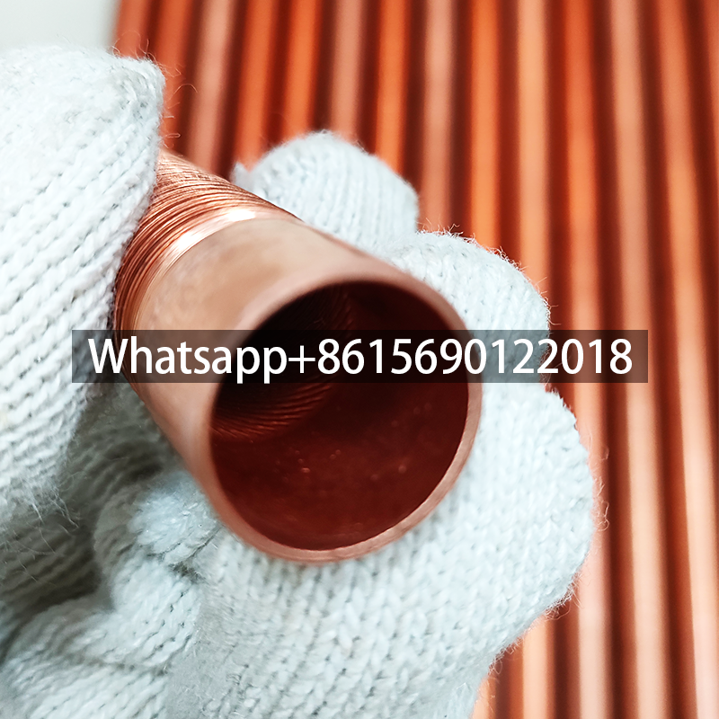
Copper Low Fin Tubes for Evaporator And Condenser
Here is the professional of the comprehensive analysis on copper low-fin tubes for evaporators and condensers:

⚙️ I. Structural Characteristics & Manufacturing Process
-
Basic Structure
- Copper low-fin tubes are formed by rolling continuous helical fins onto the outer surface of smooth copper tubes. Fin height typically ranges from 0.8–1.5 mm, pitch from 1–2 mm, and thickness ~0.2 mm.
- Key parameters (fin inner/outer diameter, pitch, height, wall thickness) directly impact heat transfer efficiency and mechanical strength.
-
Manufacturing Process
- Rolling Method (Three-Roll Skew Rolling): Copper tubes are spirally formed under mandrel support via rollers, ensuring monolithic integration of fins and base tube. This eliminates contact thermal resistance and enhances deformation resistance.
- Material: TP2 copper (thermal conductivity ~400 W/m·K) is preferred for its optimal balance of thermal performance and formability.
🔥 II. Performance Advantages & Enhanced Heat Transfer Mechanisms
-
High-Efficiency Heat Transfer
- Fin Ratio (β=2–3): Fin surface area expands to 2–3 times that of smooth tubes, increasing heat transfer efficiency by 300–400%.
- Flow Field Optimization: Fins disrupt boundary layers and induce turbulence, reducing thermal resistance—especially effective for gas/low-viscosity fluids.
-
Durability & Adaptability
- Copper’s innate corrosion resistance and antimicrobial properties suit humid environments (e.g., condensers).
- High pressure tolerance (>10 MPa) accommodates refrigerant systems under extreme pressures.

❄️🔥 III. Application Differences in Evaporators vs. Condensers
| Component | Evaporator Requirements | Condenser Requirements |
|---|---|---|
| Fin Design | Smaller pitch (prevents frost blockage) | Larger pitch (reduces fouling, eases cleaning) |
| Flow Regime | Focus on two-phase flow (liquid→vapor absorption) | Focus on vapor→liquid condensation (efficient heat dissipation) |
| Case Study | AC evaporators: dense fins, tube Ø 7–9.52 mm | Chiller condensers: wider fins, tube Ø 12.7–25.4 mm |
⚖️ IV. Material Properties & Durability
- Copper vs. Aluminum Alloy:
- Copper offers superior thermal conductivity (Al: ~237 W/m·K) but higher cost; aluminum suits air-cooled units (lightweight/corrosion-resistant).
- Copper may corrode in chloride-rich environments, requiring Zn/Ni coatings (e.g., chemical condensers).
📐 V. Technical Parameters & Design Guidelines
-
Key Parameters
- Tube Diameter: Evaporators: Ø5–9.52 mm (smaller for efficiency); Condensers: Ø12.7–25.4 mm (high-pressure resilience).
- Fin Pitch: 1.3–2.5 mm; too small increases resistance, too large reduces efficiency11,12.
- Face Velocity: 1.5–3 m/s (evaporators) or 2–3 m/s (condensers); higher speeds cause noise/pressure drop.
-
Cost Optimization
- Replacing Ø9.52 mm tubes with Ø7.94 mm or Ø7 mm reduces costs by ~10% while maintaining heat transfer capacity.

🏭 VI. Industry Applications & Trends
- HVAC&R: Chiller condensers, refrigerator evaporators (microchannel fin tubes improve efficiency by 7.9%).
- Energy/Chemical: Gas turbine waste heat recovery, reactor cooling (corrosion-resistant composite fin tubes).
- Innovation Focus:
- Microchannel Fin Tubes: Enhance refrigerant distribution uniformity, reduce pressure drop.
- Variable Pitch Fins: Adapt to temperature zones (e.g., denser fins at evaporator inlets for frost prevention).
💎 Conclusion
Copper low-fin tubes significantly boost evaporator/condenser efficiency via extended surface area + flow optimization. Monolithic construction ensures long-term reliability. Selection requires balancing tube size, fin parameters, fluid properties, cost, and corrosion resistance. Future innovations like microchannel designs and smart coatings will further expand their applications,
