Principle of Fin Tube Heat Exchanger

In heat exchangers, the heat transfer coefficients of the fluids on both sides of the heat transfer process often become uneven. To address this issue, fins are typically added to the side with the lower heat transfer coefficient.

What is a finned tube?

A finned tube, as a special heat exchanger element, features fins to enhance heat transfer. These fins significantly increase the heat transfer area of ​​the fluid, thereby improving heat transfer efficiency.

Fin tubes, also known as finned tubes or ribbed tubes, are unique in that the original surface of the tube (both the outer and inner surfaces) is covered with numerous fins, significantly expanding its original surface area. This design makes fin tubes highly efficient heat transfer elements.

Finned Tube Pipe Manufacturer and Supplier China Fin Tube Factory
Finned tube heat exchanger manufacturer and suppliers

The structure of a fin-tube heat exchanger is similar to that of a conventional shell-and-tube heat exchanger, but the core heat transfer element is replaced by finned tubes. This results in a more compact structure and a larger heat transfer area, thereby enhancing heat transfer efficiency.

Email:datangfintube@gmail.com

When should I choose fin tubes?

1. When there is a significant difference in heat transfer coefficient between the two sides of a tube, we typically add fins to the side with the lower coefficient. For example, in a boiler economizer, water flows inside the tubes while flue gas flows outside. In this case, fins are suitable for the flue gas side to enhance heat transfer. Similarly, in an air cooler, liquid flows inside the tubes while air flows outside, so fins should be installed on the air side. Another example is a steam generator, where water boils inside the tubes while flue gas flows outside. Therefore, fins should be installed on the flue gas side.

2. If the heat transfer coefficient on both sides of a tube is low, fins are added to both sides to improve heat transfer efficiency. If structural limitations prevent fins on both sides, fins on only one side may be considered. It is important to note that adding fins on only one side may not significantly improve heat transfer.

3. In some cases, such as in traditional tubular air preheaters, although both flue gas and air flow outside the tubes, the gas-to-gas heat transfer results in relatively low heat transfer coefficients on both sides, and adding fins inside the tubes is difficult. Therefore, bare tubes may be more suitable. However, in heat pipe air preheaters, the flue gas and air flow separately outside the tubes, making it easier to use finned tubes on both sides, significantly improving heat transfer.

4. When the heat transfer coefficients on both sides of the tubes are sufficiently high, such as in water-to-water heat exchangers heating cold water or in power plant condensers condensing steam, finned tubes are generally unnecessary. However, to further enhance heat transfer, threaded or corrugated tubes can be considered as an alternative to bare tubes.

What is a fin tube bundle?

A fin tube bundle is a heat exchange unit composed of multiple finned tubes arranged in a specific pattern. In a fin tube heat exchanger, one or more fin tube bundles can constitute the entire heat exchanger.

The structural components of a fin tube bundle include several key components.

1. Fin tubes, the fundamental heat transfer elements, are numerous and arranged in a specific pattern.

2. The tube box or tube sheet, which connects the ends of the finned tubes, is typically made of bent tubes or steel plates. Once the finned tubes are connected to the tube box or tube sheet, the spacing between the finned tubes is determined. The design of the tube box also ensures a continuous flow path for the fluid within the tubes.

3. The frame supports and secures the entire fin tube bundle, ensuring stability and heat transfer efficiency.

What is the arrangement of finned tubes?

In a tube bundle, the arrangement of the finned tubes is crucial, directly impacting bundle performance. There are two common arrangements: staggered and sequential.

Finned tube bundles manufacturer and supplier cangzhou datang steel pipe co., ltd

What is a staggered arrangement?

As the name suggests, staggered arrangement refers to the arrangement of tubes in a crosswise pattern in the direction of airflow.

What is a sequential arrangement?

Sequential arrangement, on the other hand, means the tubes are arranged sequentially in the direction of airflow. Each arrangement has its own advantages and is suitable for different applications. Different fin structures, such as rectangular fins or integral plate fins (also known as plate fins), also differ between staggered and sequential arrangements.

In the diagram, the arrows indicate the direction of fluid flow outside the tubes, while S1 and S2 represent the transverse and longitudinal tube spacing, respectively. Next, we will discuss the advantages and disadvantages of sequential and staggered arrangements.

A characteristic of sequential arrangement is that the fluid experiences relatively little disturbance as it flows around the tubes, resulting in a relatively low heat transfer coefficient. However, this also brings the advantage of low resistance.

In contrast, staggered arrangement exhibits different characteristics. Because the fluid experiences greater disturbance as it flows around the tubes, the heat transfer coefficient is improved. However, it is worth noting that this arrangement also increases resistance.

In practical applications, if there are no particularly strict requirements for pressure drop, the staggered arrangement is often the first choice because it can provide a higher heat transfer coefficient. When the pressure drop needs to be strictly controlled and is small, the sequential arrangement is more suitable.

Tube Box Structures

The design and selection of a fin tube heat exchanger are primarily based on the pressure of the fluid within the tubes and the heat transfer requirements. When dealing with high-pressure fluids within the tubes, it’s generally preferable to use larger diameter round tubes to construct the fin tube box to ensure structural stability and heat transfer efficiency.

Fin tube box structures

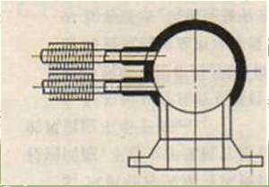
For example, in boiler applications, round tubes are often the preferred material for tube boxes, with their relatively large diameters ensuring structural stability and efficient heat exchange. In air cooler applications, square boxes are more common.

Fin tube heat exchanger square box design

The fin-tube heat exchanger’s ingenious square housing allows for simultaneous connection of multiple rows of finned tubes, providing a larger steam volume. This design is particularly important during the steam condensation process, as it ensures smooth connection between the tube housing and the multiple rows of tubes, thus meeting the requirements for efficient heat exchange.

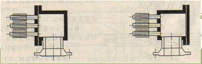
(3) When the inlet and outlet temperatures of the fluid in the tube are significantly different, the tube box may deform due to the inconsistent thermal expansion of the tube row. To address this problem, it is recommended to use a decomposed tube box design.

(4) Except for the first and last two rows of the tube bundle, it is recommended to use a one-to-one elbow connection method for the other rows.

The advantages of this design are:

First, it can improve the heat transfer efficiency. Theoretical analysis shows that the one-to-one connection can effectively prevent the mutual mixing of the fluids in each row of tubes, which will reduce the heat transfer temperature difference and heat transfer efficiency.

Second, this connection method helps to reduce the flow resistance of the fluid. Since the one-to-one connection ensures the stability of the flow cross-sectional area, it avoids the frequent expansion and contraction of the fluid in the tube.

In addition, the elbow design has the ability to “absorb” deformation caused by thermal expansion.

This is a typical finned tube bundle design, where the first and last rows utilize large-diameter round tube boxes, while the other middle rows cleverly utilize one-to-one elbow connections. This design is not only ingenious but also offers many advantages.

This device features a meticulously designed structure with seven rows of finned tubes, each containing ten tubes. These are divided into two tube passes, creating a complex structure with a total of 14 tube passes.

Finned tube heat exchanger manufacturer and suppliers
Fin tube steam condenser

Both sets of finned tube bundles are designed as square tube boxes, which likely means the pressure level of the fluid inside the tubes is not high.
This device clearly utilizes a unique structural design. Each row of finned tubes is divided into two tube passes by a carefully designed square tube box, cleverly connected by thick elbows.

Each tube pass is equipped with an outlet pipe. These outlet pipes are cleverly connected through elbows, forming the flow path within the device. This design choice is likely intended to address low flow rates within the tubes, ensuring smooth flow between tube passes and achieving efficient heat exchange.

This finned tube bundle features a unique design, consisting of four tightly packed rows of tubes. Aside from the straight-through connection of the circular inlet and outlet manifolds, the remaining sections are cleverly connected via one-to-one elbows, creating a streamlined and standardized tube bundle structure.

Blow type air cooler Industrial cooling equipment
Finned tube bundles for air coolers

The figure above shows a set of finned tube bundles for an air cooler, including a combination of square and round tube boxes, as well as one-to-one connections and full box connections using elbows.

Email:datangfintube@gmail.com

Whatsapp:+86 15690122018