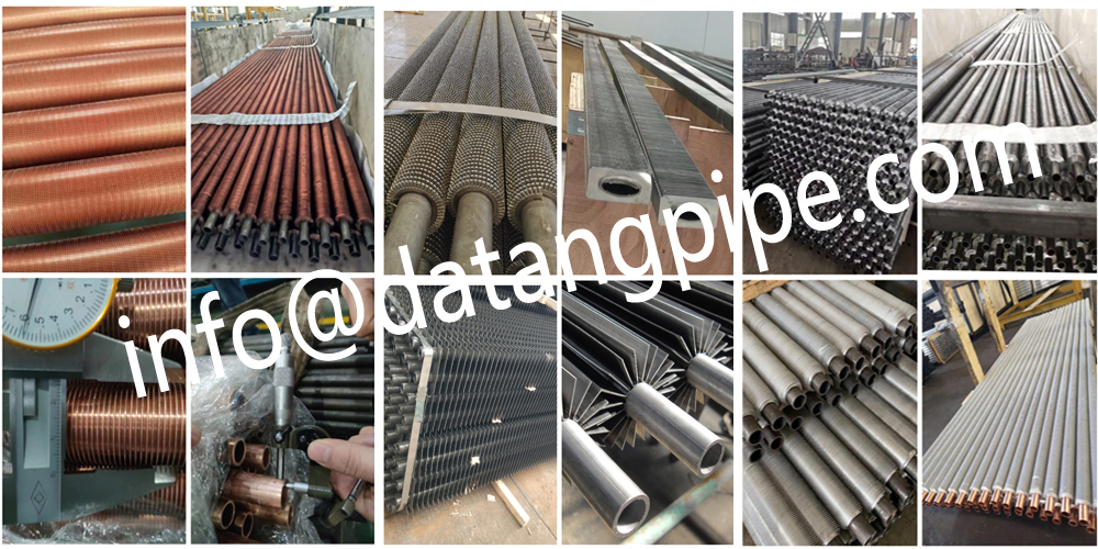
Datang is the professional of the fin tube sizing methodology:
Fin Tube Dimension Determination Methodology
The sizing of finned tubes requires comprehensive consideration of thermal performance, fluid characteristics, spatial constraints, and cost factors. The systematic approach and key parameter selection rationale are as follows:

I. Fin Tube Core Structural Parameter Design
-
Base Tube Specification
- Diameter: Selected based on medium flow rate and pressure. Residential heating typically uses DN25 (Φ32mm), while industrial settings (e.g., power plants) require DN50 (Φ60mm) or larger to withstand 1.0-2.5MPa high pressure.
- Wall Thickness: Conventional range: 2.5-3.5mm; requires 20%-30% thickening in pulsating pressure environments.
-
Fin Parameters
- Height: 12-25mm. Lower heights reduce heat dissipation area; excessive heights disrupt airflow. A 16mm height achieves 8-10 times the heat dissipation area of a bare tube.
- Spacing:
- Clean environments: 4-5mm (forced convection optimization);
- Dusty/viscous fluids: 6-12mm (anti-fouling);
- Anti-corrosion scenarios: Up to 10mm.
- Thickness: Steel fins: 0.8-1.5mm. Thinner fins reduce strength; thicker fins increase thermal resistance.
II. Fin Tube Thermal Performance Matching
-
Heat Dissipation Area Calculation
- Quantify enhancement via fin ratio (total external surface area of finned tube / original base tube area). Example: Φ25 base tube achieves a fin ratio of 10.63x.
- Formula: Fin Ratio = �total�base tube (�total includes tube surface between fins, fin tips, and front/back areas).
-
Layout Optimization
- Arrangement: Single-row (thickness 80-120mm) for confined spaces; multi-row (200-300mm) for high-power industrial applications.
- Tube Pitch: 160-230mm; staggered arrangements enhance turbulence and thermal efficiency.
III. Fin Tube Operational Condition Adaptation
-
Medium Compatibility
- Corrosive media: Use 316L stainless steel/titanium alloy; fin thickness ≥1.5mm;
- Phase-change applications: Low fins (<10mm) for evaporation; serrated fins for condensation.
-
Temperature & Pressure Matching
- High temperature (>400°C): Select SA213T11/T22 heat-resistant steel + high-frequency welding;
- Low temperature difference (ΔT<30°C): Fin ratio controlled at 15-20x; copper-aluminum composite preferred.
IV. Finned Tube Space & Cost Optimization
-
Compact Space Solutions
- Elliptical tubes or 3D internally ribbed tubes reduce volume by 30%-40%;
- Fin height reduction to 10mm (e.g., ship engine rooms).
-
Lifecycle Cost Analysis
- Optimal fin spacing: 3.5mm (7.2% cost savings vs. 4mm design);
- Industrial applications: Larger spacing (6-8mm) reduces fan energy consumption by ~2.4 million kWh/year.
V. Finned Tube Design Validation Process
- Calculate thermal load → Determine base tube diameter & fin parameters → Verify fin ratio & flow resistance;
- Special conditions (corrosion/high temp) → Material/process upgrade → Cost review;
- Space constraints → Adopt non-standard designs (e.g., curved arrangements).
Example: Custom finned tube for a pickling workshop: Base tube Φ60mm (wall 3mm), fin spacing 10mm + hot-dip galvanizing → Service life extended to 15 years.
Key Principle: Prioritize thermal requirements, then balance anti-clogging performance, corrosion resistance, and cost through fin parameter adjustment. Finalize dimensions based on spatial layout.


