Technical Product Sheet:
-
Number of Fins
Depending on the tube OD
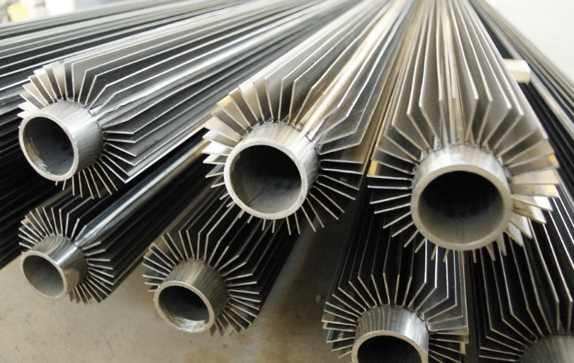
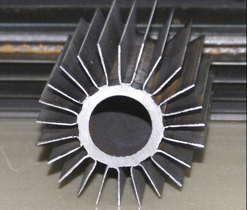
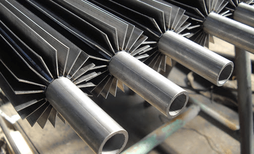
 Competitive Advantage:1. Longer working life than others ordinary welding helical fin tubes.2. Much safer and energy saving.3. Increase the heat transfer rates for viscous liquids.4. Perforated fin type used whenever drainage of liquid from fin channels become a problem.5. Longitudinal fin tubes are widely used in horizontal heat exchangers.Longitudinal Finned Tube produces by high frequency resistance welding fins in the longitudinal direction with the length of the tubes. Fin strip material shall be compatible with and suitable for standard frequency resistance welding to the specified tube material.Before applying the fins, the tube outside surface shall be properly prepared to ensure that the fin-to-tube weld is sound.The fin strip is first bend into U-shaped channel, so that each leg of the U will be a fin. The channels cut into the suitable length and oriented along the length of the tubes and resistance welded in place. The channels weld in pairs, diametrically opposed — therefore the number of fins specified always be a multiple.For a given pipe or tube size, the desired heat transfer surface area per unit length of tubes can be obtained by specifying the appropriate fin height and/or number of fins. The maximum number of fins depend upon the tube OD – larger OD tube can accommodate more number of fins.Some client specify that the longitudinal finned tubes can be “cut and twisted”. This operation consists of cutting through the fin channels circumference at specified intervals along the tube length. The fins are then bent (or “twisted”) on one side of each cut, creating a discontinuity that promotes turbulent fluid flow, thereby enhancing heat transfer efficiency.The choice of longitudinal finned tubes VS helical finned tubes seems to be governed mainly by geometric considerations. For example, some heater configurations consist of finned tubes inserted inside other tubes, longitudinal finned tubes are the obvious choice for such applications. In other cases, users prefer longitudinal finned tubes for installations where the tube will be oriented in a vertical direction — the fin orientation facilitates fluid drainage on the fin side of the tube.