How to Shape High-performance Flange Fin TubesHow to shape high-performance flange fin tubes

1. Material selection of flange fin tubes: laying the foundation for performance
Pipe material selection: As a channel for heat exchange medium, the quality of the material has a profound impact on the overall performance. Under high temperature, high pressure and corrosive complex working conditions, alloy steel pipes with strong corrosion resistance and excellent mechanical properties should be preferred.
Fin material adaptation: Fins undertake the key task of heat dissipation, and their materials must have good thermal conductivity. Aluminum has become a widely used fin material due to its high thermal conductivity, light weight and low cost. However, in some high-temperature working conditions with extremely high heat dissipation requirements, copper fins can significantly improve the heat dissipation effect with their better thermal conductivity.
When selecting fin materials, it is also necessary to fully consider their compatibility with the pipe to ensure that the two can still be closely combined during thermal expansion and contraction to reduce thermal resistance.
2. Flange fin tube structure design: key to optimizing performance
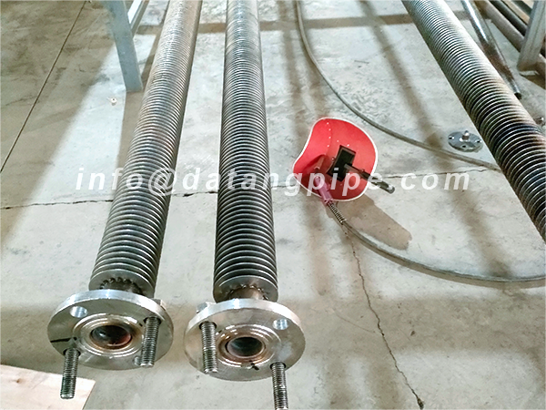
Fin shape and spacing design: Fins of different shapes, such as spiral, serrated and straight, have their own characteristics in enhancing fluid disturbance and expanding heat dissipation area.
Spiral fins can effectively increase the turbulence of the fluid and improve the heat transfer coefficient; while straight fins have the advantages of simple processing and low cost.
In actual design, it is necessary to determine the optimal fin shape through precise fluid mechanics calculation and simulation based on specific working conditions and heat exchange requirements.
Reasonable design of fin spacing is crucial. Too small spacing can easily lead to dust accumulation and blockage, hindering heat transfer; too large spacing will result in insufficient heat dissipation area and reduce heat exchange efficiency.
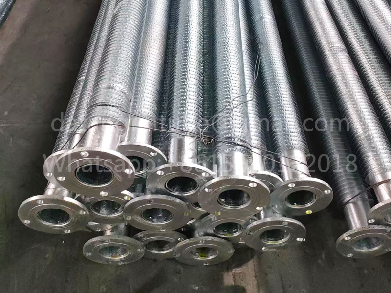
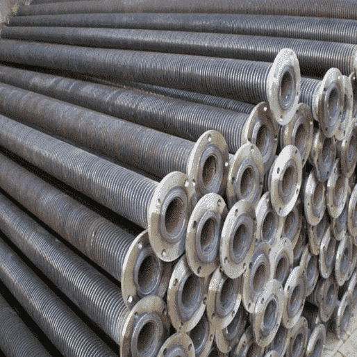
Flange connection structure optimization: As a connecting component, the structural design of the flange is directly related to the sealing and stability of the system.
The use of high-strength flanges that meet standards, such as tongue-and-groove flanges or concave-convex flanges, can effectively improve sealing performance and prevent medium leakage. At the same time, the thickness of the flange, the number and distribution of bolt holes should be reasonably designed to ensure that the connection parts are firm and reliable without deformation or loosening when bearing system pressure.

3. Flange fin tube manufacturing process: guarantee performance core
Fin and pipe welding process: welding quality is a key factor affecting heat transfer efficiency and overall strength. The use of advanced welding processes, such as high-frequency welding and laser welding, can achieve a firm connection between fins and pipes and minimize thermal resistance.
During the welding process, the welding parameters must be strictly controlled to ensure that the weld is uniform, pore-free, and crack-free, so that heat can be smoothly transferred from the pipe to the fin.
Processing accuracy control: High-precision processing is an important guarantee to ensure the accurate size and stable performance of flange fin tubes. The roundness of the pipe, the flatness of the fins, and the sealing surface accuracy of the flange all need to be guaranteed by precision processing equipment and strict quality inspection.
4. Flange fin tube quality inspection: ensure performance meets the standard
Application of non-destructive testing technology: After manufacturing, it is crucial to conduct comprehensive non-destructive testing of flange fin tubes.
Through ultrasonic testing, radiographic testing and other means, it is possible to check whether there are defects inside the weld to ensure that the welding quality meets the standards. Flaw detection of pipes can promptly detect possible cracks, sand holes and other problems to ensure the integrity of the pipes.
Strict implementation of pressure test: simulate the pressure conditions in actual operation and perform pressure test on flange finned tubes. Maintain the specified pressure for a certain period of time and carefully observe whether there are leaks, deformations, etc.
Through pressure testing, it is possible to verify its sealing and structural strength under working pressure to ensure the safety and reliability of the product in actual use.

Shaping High-Performance Finned Flange Tubes: A Technical Guide
I. Material Selection: Laying the Foundation
-
Base Tube Material
- Alloy Steel Tubes: Essential for high-temperature (>300°C), high-pressure (>10 MPa), or corrosive environments (e.g., petrochemical processing). Offers superior mechanical strength and corrosion resistance2.
- Alternatives: Stainless steel (moderate corrosion resistance) or nickel-based alloys (extreme corrosion/heat resistance).
-
Fin Material
- Aluminum Fins: Ideal for most scenarios (thermal conductivity: 200-250 W/m·K). Lightweight and cost-effective.
- Copper Fins: Preferred for ultra-high thermal efficiency (conductivity: 380-400 W/m·K) in demanding heat dissipation applications.
- Compatibility: Ensure matched thermal expansion coefficients between fins and base tubes to minimize thermal stress.
| Material Comparison | Thermal Conductivity (W/m·K) | Corrosion Resistance | Cost | Best Use Case |
|---|---|---|---|---|
| Copper Fin | 380-400 | Moderate | High | Extreme heat flux |
| Aluminum Fin | 200-250 | Low | Low | General purpose |
| Alloy Steel Tube | 20-50 | High | Medium | High-pressure/corrosive |
II. Structural Design: Optimizing Performance
-
Fin Geometry & Spacing
- Spiral Fins: Enhance turbulence (heat transfer coefficient ↑30%), suited for viscous fluids (e.g., oil refinery applications)27.
- Straight Fins: Simplify manufacturing; optimal for low-fouling gases27.
- Fin Density: 200-400 fins/meter. Excessive density causes fouling; sparse spacing reduces heat exchange area2.
-
Flange Connection
- Sealing Design: Use tongue-and-groove or raised-face flanges to prevent leakage under cyclic thermal stress2.
- Bolt Optimization: ≥8 bolt holes (ASME B16.5 standards) with uniform distribution to maintain joint integrity2.
| Fin Type Comparison | Heat Transfer Efficiency | Fouling Resistance | Manufacturing Cost | Application Example |
|---|---|---|---|---|
| Spiral Fin | ★★★★☆ | ★★☆☆☆ | High | Catalytic crackers |
| Straight Fin | ★★★☆☆ | ★★★★☆ | Low | HVAC systems |

III. Manufacturing Processes: Ensuring Reliability
-
Welding Technology
- High-Frequency Welding: Ensures metallurgical bonding with minimal thermal distortion (interfacial resistance <0.1 m²·K/W)23.
- Laser Welding: For precision joints in critical applications (e.g., ethylene cracking furnaces)2.
-
Dimensional Control
- Base tube roundness tolerance: ≤0.1 mm/m; fin flatness deviation: <0.05 mm. Ensures uniform heat flux distribution2.
IV. Quality Assurance: Validating Performance
-
Non-Destructive Testing (NDT)
- Ultrasonic Testing: Detects weld defects (pores/cracks) with sensitivity ≥Φ1 mm flaws2.
- Radiographic Inspection: Validates internal integrity in high-pressure tubes (>15 MPa)2.
-
Pressure Testing
- Hydrostatic test at 1.5× working pressure for 30 minutes (ASME Section VIII). Zero leakage tolerance2.
Conclusion
High-performance finned flange tubes demand integrated optimization of materials (corrosion-resistant alloys, matched fin-tube pairs)16, turbulence-enhanced fin designs7, precision welding3, and rigorous NDT protocols2. These strategies collectively achieve >50% higher thermal efficiency versus bare tubes while ensuring operational safety in critical industries like petrochemicals and power generation18.
